RoofViews

Building Science

How Is the Weld Strength of TPO Tested?

By Thomas J Taylor

January 28, 2016

Testing a piece of TPO with machine test equiptment.

One of the selling points of heat-weldable single-ply membranes is that fully welded seams help create a singular membrane out of multiple sheets. There are no adhesive seams to pop loose, and a properly welded seam may provide even greater protection than the rest of the membrane because it's twice as thick. This all sounds good, but how does the manufacturer test weld strength?

Here is a look at how we test weld strength at GAF:

The first step is to weld some TPO with the same equipment and settings that are used on a roof. In fact, we make many welds at varying speeds and temperatures to cover most conditions.

welder


A strip is then cut and pulled to check quality. Here's a cross-section of what a weld cut actually looks like:


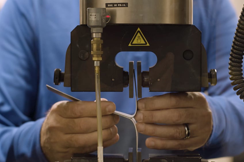
At GAF, we use machine test equipment made by Instron that enables us to measure the actual strength. The sample gets mounted between two steel jaws and pulled as shown here:


The machine records the force needed to make the pull. If you look at the center picture, you can see that the cap layer has just broken. After that, the cap peels away from the core, as can be seen in the right-hand picture. If the weld itself opens up, then it's a bad weld. The picture on the right shows what we call a film tearing bond. We've torn the cap or core film right off the membrane, exposing the reinforcement fabric. Our tester reports the force as a graph that looks like this:


This shows that it took a peak force of around 48 pound-force to break the cap or core. Then, to peel the cap from the core, it took around 20 pound-force. These are strong numbers.

We recommend roofers do a manual test weld at the start of each day, after lunch, and whenever conditions have changed. This ensures that the product welds and is the same strength day after day, mile after membrane mile!

About the Author

Thomas J Taylor, PhD is the Building & Roofing Science Advisor for GAF. Tom has over 20 year’s experience in the building products industry, all working for manufacturing organizations. He received his PhD in chemistry from the University of Salford, England, and holds approximately 35 patents. Tom’s main focus at GAF is roofing system design and building energy use reduction. Under Tom’s guidance GAF has developed TPO with unmatched weathering resistance.

Related Articles

Installation of ISO Board and TPO on a Roof
Building Science

Roof Insulation: A Positive Investment to Reduce Total Carbon

Have you ever thought about building products reducing the carbon dioxide emissions caused by your building? When considered over their useful life, materials like insulation decrease total carbon emissions thanks to their performance benefits. Read on for an explanation of how this can work in your designs.What is Total Carbon?Total carbon captures the idea that the carbon impacts of buildings should be considered holistically across the building's entire life span and sometimes beyond. (In this context, "carbon" is shorthand for carbon dioxide (CO2) emissions.) Put simply, total carbon is calculated by adding a building's embodied carbon to its operational carbon.Total Carbon = Embodied Carbon + Operational CarbonWhat is Embodied Carbon?Embodied carbon is comprised of CO2 emissions from everything other than the operations phase of the building. This includes raw material supply, manufacturing, construction/installation, maintenance and repair, deconstruction/demolition, waste processing/disposal of building materials, and transport between each stage and the next. These embodied carbon phases are indicated by the gray CO2 clouds over the different sections of the life cycle in the image below.We often focus on "cradle-to-gate" embodied carbon because this is the simplest to calculate. "Cradle-to-gate" is the sum of carbon emissions from the energy consumed directly or indirectly to produce the construction materials used in a building. The "cradle to gate" approach neglects the remainder of the embodied carbon captured in the broader "cradle to grave" assessment, a more comprehensive view of a building's embodied carbon footprint.What is Operational Carbon?Operational carbon, on the other hand, is generated by energy used during a building's occupancy stage, by heating, cooling, and lighting systems; equipment and appliances; and other critical functions. This is the red CO2 cloud in the life-cycle graphic. It is larger than the gray CO2 clouds because, in most buildings, operational carbon is the largest contributor to total carbon.What is Carbon Dioxide Equivalent (CO2e)?Often, you will see the term CO2e used. According to the US Environmental Protection Agency (EPA), "CO2e is simply the combination of the pollutants that contribute to climate change adjusted using their global warming potential." In other words, it is a way to translate the effect of pollutants (e.g. methane, nitrous oxide) into the equivalent volume of CO2 that would have the same effect on the atmosphere.Today and the FutureToday, carbon from building operations (72%) is a much larger challenge than that from construction materials' embodied carbon (28%) (Architecture 2030, 2019). Projections into 2050 anticipate the operations/embodied carbon split will be closer to 50/50, but this hinges on building designs and renovations between now and 2050 making progress on improving building operations.Why Insulation?Insulation, and specifically continuous insulation on low-slope roofs, is especially relevant to the carbon discussion because, according to the Embodied Carbon 101: Envelope presentation by the Boston Society for Architecture: Insulation occupies the unique position at the intersection of embodied and operational carbon emissions for a building. Insulation is the only building material that directly offsets operational emissions. It can be said to pay back its embodied carbon debt with avoided emissions during the building's lifetime.A Thought Experiment on Reducing Total CarbonTo make progress on reducing the total carbon impact of buildings, it is best to start with the largest piece of today's pie, operational carbon. Within the range of choices made during building design and construction, not all selections have the same effect on operational carbon.When making decisions about carbon and energy reduction strategies, think about the problem as an "investment" rather than a "discretionary expense." Discretionary expenses are easier to reduce or eliminate by simply consuming less. In the example below, imagine you are flying to visit your client's building. Consider this a "discretionary expense." The input on the far left is a given number of kilograms of carbon dioxide equivalent (CO2e) generated for the flight, from the manufacturing of the airplane, to the fuel it burns, to its maintenance. The output is the flight itself, which creates CO2 emissions, but no durable good. In this case, the only CO2 reduction strategy you can make is to make fewer or shorter flights, perhaps by consolidating visits, employing a local designer of record, or visiting the building virtually whenever possible. Now consider the wallpaper you might specify for your client's building. It involves a discretionary expenditure of CO2e, in this case, used to produce a durable good. However, this durable good is a product without use-phase benefits. In other words, it cannot help to save energy during the operational phase of the building. It has other aesthetic and durability benefits, but no operational benefits to offset the CO2 emissions generated to create it. Your choices here are expanded over the previous example of an airplane flight. You can limit CO2 by choosing a product with a long useful life. You can also apply the three Rs: reduce the quantity of new product used, reuse existing material when possible, and recycle product scraps at installation and the rest at the end of its lifespan. In the final step in our thought experiment, consider the insulation in your client's building. As before, we must generate a certain amount of CO2e to create a durable good. In this case, it's one with use-phase benefits. Insulation can reduce operational energy by reducing heat flow through the building enclosure, reducing the need to burn fuel or use electricity to heat and cool the building. The good news is that, in addition to the other strategies considered for the flight and the wallpaper, here you can also maximize operational carbon savings to offset the initial embodied carbon input. And, unlike the discretionary nature of some flights and the often optional decision to use furnishings like wallpaper, heating and cooling are necessary for the functioning of almost all occupied buildings.Based on this example, you can consider building products with operational benefits, like insulation, as an "investment." It is appropriate to look at improving the building enclosure and understanding what the return on the investment is from a carbon perspective. As the comparison above demonstrates, if you have a limited supply of carbon to "invest", putting it into more roof insulation is a very smart move compared to "spending" it on a discretionary flight or on a product without use-phase carbon benefits, such as wallpaper.This means we should be careful not to measure products like insulation that save CO2e in the building use-phase savings only by their embodied carbon use, but by their total carbon profile. So, how do we calculate this?Putting It to the TestWe were curious to know just how much operational carbon roof insulation could save relative to the initial investment of embodied carbon required to include it in a building. To understand this, we modeled the US Department of Energy's (DOE) Standalone Retail Prototype Building located in Climate Zone 4A to comply with ASHRAE 90.1-2019 energy requirements. We took the insulation product's embodied energy and carbon data from the Polyisocyanurate Insulation Manufacturers Association's (PIMA) industry-wide environmental product declaration (EPD).To significantly reduce operational carbon, the largest carbon challenge facing buildings today, the returns on the investment of our building design strategies need to be consistent over time. This is where passive design strategies like building enclosure improvements really shine. They have much longer service lives than, for example, finish materials, leading to sustained returns.Specifically, we looked here at how our example building's roof insulation impacted both embodied and operational carbon and energy use. To do this, we calculated the cumulative carbon savings over the 75-year life of our model building. In our example, we assumed R-30 insulation installed at the outset, increased every 20 years by R-10, when the roof membrane is periodically replaced.In our analysis, the embodied CO2e associated with installing R-30 (shown by the brown curve in years -1 to 1), the embodied carbon of the additional R-10 of insulation added every 20 years (too small to show up in the graph), and the embodied carbon represented by end-of-life disposal (also too small to show up) are all taken into account. About five months after the building becomes operational, the embodied carbon investment of the roof insulation is dwarfed by the operational savings it provides. The initial and supplemental roof insulation ultimately saves a net of 705 metric tons of carbon over the life of the building.If you want to see more examples like the one above, check out PIMA's study, conducted by the consulting firm ICF. The research group looked at several DOE building prototypes across a range of climate zones, calculating how much carbon, energy, and money can be saved when roof insulation is upgraded from an existing baseline to current code compliance. Their results can be found here. Justin Koscher of PIMA also highlighted these savings, conveniently sorted by climate zone and building type, here.Support for Carbon Investment DecisionsSo how can you make sure you address both operational and embodied carbon when making "carbon investment" decisions? We've prepared a handy chart to help.First, when looking at lower-embodied-carbon substitutions for higher-embodied-carbon building materials or systems (moving from the upper-left red quadrant to the lower-left yellow quadrant in the chart), ensure that the alternatives you are considering have equivalent performance attributes in terms of resilience and longevity. If an alternative material or system has lower initial embodied carbon, but doesn't perform as well or last as long as the specified product, then it may not be a good carbon investment. Another consideration here is whether or not the embodied carbon of the alternative is released as emissions (i.e. as part of its raw material supply or manufacturing, or "cradle to gate" stages), or if it remains in the product throughout its useful life. In other words, can the alternative item be considered a carbon sink? If so, using it may be a good strategy.Next, determine if the alternative product or system can provide operational carbon savings, even if it has high embodied energy (upper-right yellow quadrant). If the alternative has positive operational carbon impacts over a long period, don't sacrifice operational carbon savings for the sake of avoiding an initial embodied product carbon investment when justified for strategic reasons.Last, if a product has high operational carbon savings and relatively low embodied carbon (lower-right green quadrant), include more of this product in your designs. The polyiso roof insulation in our example above fits into this category. You can utilize these carbon savings to offset the carbon use in other areas of the design, like aesthetic finishes, where the decision to use the product may be discretionary but desired.When designing buildings, we need to consider the whole picture, looking at building products' embodied carbon as a potential investment yielding improved operational and performance outcomes. Our design choices and product selection can have a significant impact on total carbon targets for the buildings we envision, build, and operate.Click these links to learn more about GAF's and Siplast's insulation solutions. Please also visit our design professional and architect resources page for guide specifications, details, innovative green building materials, continuing education, and expert guidance.We presented the findings in this blog in a presentation called "Carbon and Energy Impacts of Roof Insulation: The Whole[-Life] Story" given at the BEST6 Conference on March 19, 2024 in Austin, Texas.References:Architecture 2030. (2019). New Buildings: Embodied Carbon. https://web.archive.org/web/20190801031738/https://architecture2030.org/new-buildings-embodied/ Carbon Leadership Forum. (2023, April 2). 1 - Embodied Carbon 101. https://carbonleadershipforum.org/embodied-carbon-101/

By Authors Elizabeth Grant

September 13, 2024

An aerial shot of the student housing building on the Texas A&M campus.
Building Science

Are Hybrid Roof Assemblies Worth the Hype?

How can roofing assemblies contribute to a building's energy efficiency, resiliency, and sustainability goals? Intentional material selection will increase the robustness of the assembly including the ability to weather a storm, adequate insulation will assist in maintaining interior temperatures and help save energy, and more durable materials may last longer, resulting in less frequent replacements. Hybrid roof assemblies are the latest roofing trend aimed at contributing to these goals, but is all the hype worth it?What is a hybrid roof assembly?A hybrid roof assembly is where two roofing membranes, composed of different technologies, are used in one roof system. One such assembly is where the base layers consist of asphaltic modified bitumen, and the cap layer is a reflective single-ply membrane such as a fleece-back TPO or PVC. Each roof membrane is chosen for their strengths, and together, the system combines the best of both membranes. A hybrid system such as this has increased robustness, with effectively two plies or more of membrane.Asphaltic membranes, used as the first layer, provide redundancy and protection against punctures as it adds overall thickness to the system. Asphaltic systems, while having decades of successful roof installations, without a granular surface may be vulnerable to UV exposure, have minimal resistance to ponding water or certain chemical contaminants, and are generally darker in color options as compared to single ply surfacing colors choices. The addition of a single-ply white reflective membrane will offset these properties, including decreasing the roof surface temperatures and potentially reducing the building's heat island effect as they are commonly white or light in color. PVC and KEE membranes may also provide protection where exposure to chemicals is a concern and generally hold up well in ponding water conditions. The combination of an asphaltic base below a single-ply system increases overall system thickness and provides protection against punctures, which are primary concerns with single-ply applications.Pictured Above: EverGuard® TPO 60‑mil Fleece‑Back MembraneOlyBond 500™ AdhesiveRUBEROID® Mop Smooth MembraneMillennium Hurricane Force ® 1-Part Membrane AdhesiveDensDeck® Roof BoardMillennium Hurricane Force ® 1-Part Membrane AdhesiveEnergyGuard™ Polyiso InsulationMillennium Hurricane Force ® 1-Part Membrane AdhesiveConcrete DeckPictured Above: EverGuard® TPO 60‑mil Fleece‑Back MembraneGAF LRF Adhesive XF (Splatter)RUBEROID® HW Smooth MembraneDrill‑Tec™ Fasteners & PlatesDensDeck® Prime Gypsum BoardEnergyGuard™ Polyiso InsulationEnergyGuard™ Polyiso InsulationGAF SA Vapor Retarder XLMetal DeckWhere are hybrid roof assemblies typically utilized?Hybrid roof assemblies are a common choice for K-12 & higher education buildings, data centers, and hospitals due to their strong protection against leaks and multi-ply system redundancy. The redundancy of the two membrane layers provides a secondary protection against leaks if the single-ply membrane is breached. Additionally, the reflective single-ply membrane can result in lower rooftop temperatures. The addition of a reflective membrane over a dark-colored asphaltic membrane will greatly increase the Solar Reflectance Index (SRI) of the roof surface. SRI is an indicator of the ability of a surface to return solar energy into the atmosphere. In general, roof material surfaces with a higher SRI will be cooler than a surface with a lower SRI under the same solar energy exposure. A lower roof surface temperature can result in less heat being absorbed into the building interior during the summer months.Is a hybrid only for new construction?The advantage of a hybrid roof assembly is significant in recover scenarios where there is an existing-modified bitumen or built-up roof that is in overall fair condition and with little underlying moisture present. A single ply membrane can be installed on top of the existing roof system without an expensive and disruptive tear-off of the existing assembly. The addition of the single-ply membrane adds reflectivity to the existing darker colored membrane and increases the service life of the roof assembly due to the additional layer of UV protection. Additionally, the single-ply membrane can be installed with low VOC options that can have minimum odor and noise disturbance if construction is taking place while the building is occupied.Is the hybrid assembly hype worth it?Absolutely! The possibility to combine the best aspects of multiple roofing technologies makes a hybrid roof assembly worth the hype. It provides the best aspects of a single-ply membrane including a reflective surface for improved energy efficiency, and increased protection against chemical exposure and ponding water, while the asphaltic base increases overall system waterproofing redundancy, durability and protection. The ability to be used in both new construction and recover scenarios makes a multi-ply hybrid roof an assembly choice that is here to stay.Interested in learning more about designing school rooftops? Check out available design resources school roof design resources here. And as always, feel free to reach out to the Building & Roofing Science team with questions.This article was written by Kristin M. Westover, P.E., LEED AP O+M, Technical Manager, Specialty Installations, in partnership with Benjamin Runyan, Sr. Product Manager - Asphalt Systems.

By Authors Kristin Westover

December 28, 2023

Flat roof with hot air welded pvc membrane waterproofing for ballasted system
Building Science

Thermal Bridging Through Roof Fasteners: Why the Industry Should Take Note

What is going on here?No, this roof does not have measles, it has a problem with thermal bridging through the roof fasteners holding its components in place, and this problem is not one to be ignored.As building construction evolves, you'd think these tiny breaches through the insulating layers of the assembly, known as point thermal bridges, would matter less and less. But, as it happens, the reverse is true! The tighter and better-insulated a building, the bigger the difference all of the weak points, in its thermal enclosure, make. A range of codes and standards are beginning to address this problem, though it's important to note that there is often a time lag between development of codes and their widespread adoption.What Is the Industry Doing About It?Long in the business of supporting high-performance building enclosures, Phius (Passive House Institute US) provides a Fastener Correction Calculator along with a way to calculate the effect of linear thermal bridges (think shelf angles, lintels, and so on). By contrast, the 2021 International Energy Conservation Code also addresses thermal bridging, but only considers framing materials to be thermal bridges, and actually pointedly ignores the effects of point loads like fasteners in its definition of continuous insulation: "insulation material that is continuous across all structural members without thermal bridges other than fasteners and service openings" (Section C202). Likewise, The National Energy Code of Canada for Buildings: 2020 addresses thermal bridging of a number of building components, but also explicitly excludes fasteners: "in calculating the overall thermal transmittance of assemblies…fasteners need not be taken into account" (Section 3.1.1.7.3). Admittedly, point thermal bridges are often excluded because it is challenging to assess them with simple simulation tools.Despite this, researchers have had a hunch for decades that thermal bridging through the multitude of fasteners often used in roofs is in fact significant enough to warrant study. Investigators at the National Bureau of Standards, Oak Ridge National Laboratory, the National Research Council Canada, and consulting firms Morrison Hershfield and Simpson Gumpertz & Heger (SGH), have conducted laboratory and computer simulation studies to analyze the effects of point thermal bridges.Why Pay Attention Now?The problem has been made worse in recent years because changes in wind speeds, design wind pressures, and roof zones as dictated by ASCE 7-16 and 7-22 (see blogs by Jim Kirby and Kristin Westover for more insight), mean that fastener patterns are becoming denser in many cases. This means that there is more metal on average, per square foot of roof, than ever before. More metal means that more heat escapes the building in winter and enters the building in summer. By making our buildings more robust against wind uplift to meet updated standards, we are in effect making them less robust against the negative effects of hot and cold weather conditions.So, how bad is this problem, and what's a roof designer to do about it? A team of researchers at SGH, Virginia Tech, and GAF set out to determine the answer, first by simplifying the problem. Our plan was to develop computer simulations to accurately anticipate the thermal bridging effects of fasteners based on their characteristics and the characteristics of the roof assemblies in which they are used. In other words, we broke the problem down into parts, so we could know how each part affects the problem as a whole. We also wanted to carefully check the assumptions underlying our computer simulation and ensure that our results matched up with what we were finding in the lab. The full paper describing our work was delivered at the 2023 IIBEC Convention and Trade Show, but here are the high points, starting with how we set up the study.First, we began with a simple 4" polyisocyanurate board (ISO), and called it Case A-I.Next, we added a high-density polyisocyanurate cover board (HD ISO), and called that Case A-II.Third, we added galvanized steel deck to the 4" polyiso, and called that Case A-III.Finally, we created the whole sandwich: HD ISO and ISO over steel deck, which was Case A-IV.Note that we did not include a roof membrane, substrate board, air barrier, or vapor retarder in these assemblies, partly to keep it simple, and partly because these components don't typically add much insulation value to a roof assembly.The cases can be considered base cases, as they do not yet contain a fastener. We needed to simulate and physically test these, so we could understand the effect that fasteners have when added to them.We also ran a set of samples, B-I through B-IV, that corresponded with cases A-I through A-IV above, but had one #12 fastener, 6" long, in the center of the 2' x 2' assembly, with a 3" diameter insulation plate. These are depicted below. The fastener penetrated the ISO and steel deck, but not the HD ISO.One visualization of the computer simulation is shown here, for Case B-IV. The stripes of color, or isotherms, show the vulnerability of the assembly at the location of the fastener.What did we find? The results might surprise you.First, it's no surprise that the fastener reduced the R-value of the 2' x 2' sample of ISO alone by 4.2% in the physical sample, and 3.4% in the computer simulation (Case B-I compared to Case A-I).When the HD ISO was added (Cases II), R-value fell by 2.2% and 2.7% for the physical experiment and computer simulation, respectively, when the fastener was added. In other words, adding the fastener still caused a drop in R-value, but that drop was considerably less than when no cover board was used. This proved what we suspected, that the HD ISO had an important protective effect against the thermal bridging caused by the fastener.Next, we found that the steel deck made a big difference as well. In the physical experiment, the air contained in the flutes of the steel deck added to the R-value of the assembly, while the computer simulation did not account for this effect. That's an item that needs to be addressed in the next phase of research. Despite this anomaly, both approaches showed the same thing: steel deck acts like a radiator, exacerbating the effect of the fastener. In the assemblies with just ISO and steel deck (Cases III), adding a fastener resulted in an R-value drop of 11.0% for the physical experiment and 4.6% for the computer simulation compared to the assembly with no fastener.Finally, the assemblies with all the components (HD ISO, ISO and steel deck, a.k.a. Cases IV) showed again that the HD ISO insulated the fastener and reduced its negative impact on the R-value of the overall assembly. The physical experiment had a 6.1% drop (down from 11% with no cover board!) and the computer simulation a 4.2% drop (down from 4.6% with no cover board) in R-value when the fastener was added.What Does This Study Tell Us?The morals of the study just described are these:Roof fasteners have a measurable impact on the R-value of roof insulation.High-density polyisocyanurate cover boards go a long way toward minimizing the thermal impacts of roof fasteners.Steel deck, due to its high conductivity, acts as a radiator, amplifying the thermal bridging effect of fasteners.What Should We Do About It?As for figuring out what to do about it, this study and others first need to be extended to the real world, and that means making assumptions about parameters like the siting of the building, the roof fastener densities required, and the roof assembly type.Several groups have made this leap from looking at point thermal bridges to what they mean for a roof's overall performance. The following example was explored in a paper by Taylor, Willits, Hartwig and Kirby, presented at the RCI, Inc. Building Envelope Technology Symposium in 2018. In that paper, the authors extended computer simulation results from a 2015 paper by Olson, Saldanha, and Hsu to a set of actual roofing scenarios. They found that the installation method has a big impact on the in-service R-value of the roof.They assumed a 15,000-square-foot roof, fastener patterns and densities based on a wind uplift requirement of 120 pounds per square foot, and a design R-value of R-30. In this example, a traditional mechanically attached roof had an in-service R-value of only R-25, which is a 17% loss compared to the design R-value.An induction-welded roof was a slight improvement over the mechanically attached assembly, with an in-service value of only R-26.5 (a 12% loss compared to the design R-value).Adhering instead of fastening the top layer of polyiso resulted in an in-service R-value of R-28.7 (a 4% loss compared to the design R-value).Finally, in their study, an HD polyiso board was used as a mechanically fastened substrate board on top of the steel deck, allowing both layers of continuous polyiso insulation and the roof membrane to be adhered. Doing so resulted in an in-service R-value of R-29.5, representing only a 1.5% loss compared to the design R-value.To operationalize these findings in your own roofing design projects, consider the following approaches:Consider eliminating roof fasteners altogether, or burying them beneath one or more layers of insulation. Multiple studies have shown that placing fastener heads and plates beneath a cover board, or, better yet, beneath one or two layers of staggered insulation, such as GAF's EnergyGuard™ Polyiso Insulation, can dampen the thermal bridging effects of fasteners. Adhering all or some of the layers of a roof assembly minimizes unwanted thermal outcomes.Consider using an insulating cover board, such as GAF's EnergyGuard™ HD or EnergyGuard™ HD Plus Polyiso cover board. Installing an adhered cover board in general is good roofing practice for a host of reasons: they provide enhanced longevity and system performance by protecting roof membranes and insulation from hail damage; they allow for enhanced wind uplift and improved aesthetics; and they offer additional R-value and mitigate thermal bridging as shown in our recent study.Consider using an induction-welded system that minimizes the number of total roof fasteners by dictating an even spacing of insulation fasteners. The special plates of these fasteners are then welded to the underside of the roof membrane using an induction heat tool. This process eliminates the need for additional membrane fasteners.Consider beefing up the R-value of the roof insulation. If fasteners diminish the actual thermal performance of roof insulation, building owners are not getting the benefit of the design R-value. Extra insulation beyond the code minimum can be specified to make up the difference.Where Do We Go From Here?Some work remains to be done before we have a computer simulation that more closely aligns with physical experiments on identical assemblies. But, the two methods in our recent study aligned within a range of 0.8 to 6.7%, which indicates that we are making progress. With ever-better modeling methods, designers should soon be able to predict the impact of fasteners rather than ignoring it and hoping for the best.Once we, as a roofing industry, have these detailed computer simulation tools in place, we can include the findings from these tools in codes and standards. These can be used by those who don't have the time or resources to model roof assemblies using a lab or sophisticated modeling software. With easy-to-use resources quantifying thermal bridging through roof fasteners, roof designers will no longer be putting building owners at risk of wasting energy, or, even worse, of experiencing condensation problems due to under-insulated roof assemblies. Designers will have a much better picture of exactly what the building owner is getting when they specify a roof that includes fasteners, and which of the measures detailed above they might take into consideration to avoid any negative consequences.This research discussed in this blog was conducted with a grant from the RCI-IIBEC Foundation and was presented at IIBEC's 2023 Annual Trade Show and Convention in Houston on March 6. Contact IIBEC at https://iibec.org/ or GAF at BuildingScience@GAF.com for more information.

By Authors Elizabeth Grant

November 17, 2023

Don't miss another GAF RoofViews post!

Subscribe now